Friday, 27 February 2009

(V642-2) TECHNICAL DESCRIPTION

for ease of downloading i have split this publication into 5 sections as listed below:-

TRUCK, CARGO, HMLC, 5 TON, 6 X 6
ALVIS / STALWART MK 2 (FV622)
TRUCK, CARGO, HMLC, with winch & crane,
5 TON, 6 X 6, ALVIS / STALWART (FV623)

TECHNICAL HANDBOOK - TECHNICAL DESCRIPTION
V 642-2
SUBJECT INDEX

SECTION ONE (8.1Mb)
Introduction
Engine
Engine Mounting
Engine Lubrication System
Cooling System


SECTION TWO (7.1Mb)
Exhaust System
Transmission -
clutch
gearbox
transfer box
bevel boxes & transmission shafts
tracta shafts & roadwheel hub reduction gears


SECTION THREE (1.8Mb)
Braking System


SECTION FOUR (4.4Mb)
Steering System
Suspension
Roadwheels & Tyres
Propulsion System


SECTION FIVE (3.1Mb)
Auxiliary Pumps
Winch
Crane
Electrical Equipment


this document has been scanned from micro fiche, some of the images apear in negative, when i have time i hope to replace the photos with better quality ones. If there is a section or publication you need email me & i will try to upload it first

compressor


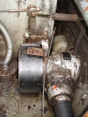
compressor mounted on the end of the top crank, runs well and no longer rattles like a tin of rocks, that distinctive clanking is OK when you know what it is (slack in the drive shaft) but almost embarrassing as it must sound like a serious problem to anyone not knowing.
bottom right is the power steering pump mounted to one side of the generator drive housing but that has now been moved to the side of the hull with a belt drive fabricated as it was running way too fast.
Posted by Picasa

diesel engine

Posted by Picasa

New bump stops


Posted by Picasa

Refurbished bump stops

all painted and ready to fit
the rubber inside the piston assembly in good shape
rubber on piston in good shape also
the end of the shaft got mashed so was cut off and replaced
Posted by Picasa

Tuesday, 24 February 2009

the sound of diesel

new diesel tank

the old & the new, the bottom of the oil drum is dented in so that it clears the drive shafts to the front bevel boxes

from left to right you can see the inlet,breather, return & outlet (good bita braising cheers Baz)

hope to rig some kind of fuel gauge into the drums original filler hole


still needs strapping down but a good fit and leaves a bit more space and will certainly be easier to get in and out if needed
at the top of the picture is the hydraulic tank usualy hidded by the back of the cab
Posted by Picasa

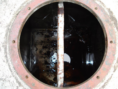
old petrol tank


the old petrol tank, forgetting the inherant condensation problems if not kept full can you image how much petrol it takes to get just a few inches from the bottom due to the huge footprint


looking down inside you can see one of the internal baffles

a lot of surface rust on the inside
and a big pile of crap in the corner !
Posted by Picasa

Handbrake seal


new oil seal in the handbrake assembly

the brake drum


and shaft coming out of front bevel box
Posted by Picasa

Sunday, 22 February 2009

(V644)Pt.1 - FV622 DETAILED ACTIVITY GUIDE

TRUCK, CARGO,HIGH MOBILITY LOAD CARRIER, 5-TON, 6X6,
ALVIS STALWART, MK 2, FV 622
DETAILED ACTIVITY GUIDE SUPPLEMENT 1 to 10
FOR :-

1. removing and fitting of main engine assembly
2. removing and fitting of main gearbox and transfer box assembly (engine fitted)
3. removing and fitting of main gearbox and transfer box assembly (engine removed)
4. removing and fitting of propulsion unit, Mk 2
5. removing and fitting of front bevel box assembly
6. removing and fitting of center bevel box assembly
7. removing and fitting of rear bevel box assembly
8. removing and fitting of the steering gear assembly
9. removing and fitting of wheel station complete
10. bleeding of accelerator, brakes, clutch, choke and steering assemblies

this document can be viewed by clicking HERE or on the green title above, its 6mb in size

Monday, 16 February 2009

FRONT BEVEL BOXES

With the fuel tank removed you can see the front bevel boxes including the handbrake assembly, also the hand bilge pump pipe and filter in the middle.

Right-side
Left-side
The hand opperated bilge pump can now be seen, it is usualy hidded by the rear of the cab panel & the hydraulic tank, the large rubber pipe on the left side is the fuel filler pipe, the original tank is to be replaced by a 50Gal. oil drum as the original tank is not only too large causing condensation problems if not kept filled but was also not in the best of shape.
Posted by Picasa

dirty, dirty oil

With the cover plug (F16-49) removed you can see the drain plug (F16-19) (this picture is looking upwards) The oil pipe had been replaced and was not long enough to clear removal of the cover plug, another was made but we are going to install two grease nipples instead ( i know it should be an oil-way NOT grease)
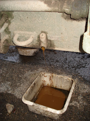
Here is some treacle looking "oil" as drained from the Transfer & centre bevel boxes, after draining overnight we collected about 3/4 of a bowl. Once drained deisel was poured into the tranfer box & the stolly was "agitated" with a large fork-lift before draining off a liquid reminicent of Trophy Best Bitter. With fresh oil in all the bevel boxes the poor old stolly will be a lot happier.
Posted by Picasa

COLLAPSED TAPERED ROLLER BEARING

"Well theres Ya' Problem!"

Front Lefthand side had been making a LOT of noise, a lack of oil & this collapsed bearing was the cause.
Posted by Picasa

Wednesday, 4 February 2009

DOWTY JETS


& Please Remember


Milfoil forms very dense mats of vegetation on the
surface of the water. These mats interfere with
recreational activities such as swimming, fishing,
water skiing, and boating.

Monday, 2 February 2009

old news 26/07/07


an old news clipping, its not us but one day.......
Posted by Picasa